- Home
- Game of Life
- Bubbles Game
- Glass Renderer
- Sentry AI Demo
- Font/Graphics
Description:
This is a very simple program (as far as the user is concerned) which utilizes some relatively complex geometric calculations. The program models the refraction of light through a glass sphere by means of distorting a backdrop. The refraction is modeled accurately according to Snell's Law (n1 sin theta1 = n2 sin theta2). The index of refraction of air is assumed to be exactly 1.0 and the index of refraction of glass begins at 1.52 (although it may be adjusted by the user).
The rendering works by ray tracing forward from the viewer to the backdrop (instead of from a light source back to the viewer, as occurs in nature). The pixel location is converted into a point in space (on the backdrop) and the angle from the viewer to this point is calculated. If the line from the viewer to this point intersects the sphere, the angle of incidence is calculated and the interior refractive angle is derived by Snell's Law. Due to the nature of a sphere, this will be the same as the outgoing angle of incidence. Then the exterior refractive angle (on the back of the sphere) is the same as the original angle of incidence with the sphere. Subtracting the differences in each pair of angles from the initial viewing angle gives an "absolute" angle from the viewer to the backdrop--that is, the angle from the viewer to the point on the backdrop which is seen through the sphere at the given viewing angle. The spatial position of this point is derived and converted into pixels. If the pixel it points to is outside the bounds of the backdrop, it behaves as if a mirror image of the backdrop continued beyond the borders (alternatives include basic wraparound of the image or simply drawing black beyond the edge).
A more detailed explanation of the process follows:
Certain assumptions are made. First, the backdrop is defined as a plane at a given distance from (and normal to) the camera. Also given are the pixel size of the backdrop, the distance between the backdrop and the sphere, the radius of the sphere, the field-of-view of the camera, and the indices of refraction of air and glass. From the field-of-view and the size of the backdrop image, a conversion can be calculated from physical space to pixels. This is defined by the equation backdropWidth * 2.0 * sin(fieldOfView / 2.0), which is the ratio of a pixel to an arbitrary unit of length on the backdrop relative to the camera.
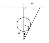
Example 1
In order to find the on-screen drawing area, the square bordering the sphere's projection on the backdrop is calculated. As illustrated in Example 1, the projected radius is given by w = tan(theta) * cameraDistance. Theta is given by sin-1(radius / a), where a is (cameraDistance - sphereDistance). Each side of the square bounding the sphere on-screen is equal to twice this length.
Once the bound is defined, the program iterates over each pixel in the box. A conversion is made from Cartesian to polar coordinates: a point (x, y) is given as a distance r = sqrt(x2 + y2) and an azimuth angle. The symmetry of a sphere allows the azimuth angle to be ignored for the time being. If the distance r is greater than the radius of the projected circle, that point is ignored. Otherwise, the following steps are performed to trace a ray to a point on the backdrop.
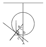
Example 2
First, the angle of incidence is required. This is the complement of angle B in Example 2 above. Angle B may be determined by the equation sin-1(b sin A / a), since sides a and b are known and angle A is given by the equation A = tan-1(r / cameraDistance). It should be noted that a triangle given by ASS (angle-side-side) is ambiguous; in this case, there are actually two angles which satisfy angle B. However, this is not a problem; since one angle is simply the complement of the other, this operation on any calculator will clearly either return B or the angle of incidence (in this program, it gives the angle of incidence).
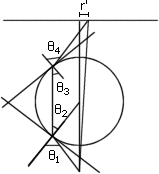
Example 3
Using Snell's Law, the refractive angle is found to be theta2 = sin-1(n1 sin theta1 / n2). Again, the properties of a sphere simplify the process, as the internal angle of incidence on the opposite side of the sphere will always be the same as this refractive angle. The external refractive angle is therefore the same as the initial angle of incidence. Finally, an "absolute" angle may be found by the equation absAngle = A - (theta1 - theta2) - (theta4 - theta3), or simply absAngle = A - 2 * (theta1 - theta2).
Now a distance r' = cameraDistance * tan(absAngle) may be found. The azimuth angle from the original Cartesian to polar conversion is paired with distance r' to define a point on the backdrop. This is converted back to Cartesian coordinates (and then back into pixels), and finally the color of that pixel may be obtained and displayed at the correct position on-screen.
Controls:
Up/Down: Move the sphere further from/closer to the viewer, respectively
Left/Right: Decrease/increase the index of refraction of glass, respectively
Code files:
font.cpp
Font class, contains data and methods for font objects
font.h
Font class header
gfx.cpp
Graphics primitives library (points, lines, circles, etc.)
glass.cpp
Main program